Here is collection of Technical Drawing Past Questions and Answers PDF to assist you with your studies for the West African Senior School Certificate Examination (WASSCE) for both School and GCE candidates.
If you are in your last stage of Secondary School Education (May/June) or not in the School system (GCE), the importance of using old exam papers in preparing for your West African Senior School Certificate Examination (WASSCE), cannot be over emphasized. By using past exam papers as part of your preparation, you can find out what you already know. By the same token you also find out what you do not know well enough or don’t know at all.
What is more, the Technical Drawing Past Questions and Answers PDF can also be used as an organizational tool to manage your time better, as you can plan according to each section of the paper.
As a matter of fact, revision is more better than memorizing facts and going over notes. You can practice for your Technical Drawing Past Questions and Answers PDF by answering real questions from past papers. This will give you a better chance of passing.
Technical Drawing Past Questions and Answers PDF
Click on the year you want to start your revision.
- Technical Drawing Past Questions and Answers PDF 2023
- Technical Drawing Past Questions and Answers PDF 2020
- Technical Drawing Past Questions and Answers PDF 2021
Technical Drawing Paper 3

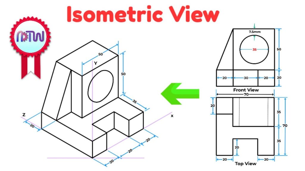
Technical Drawing Isometric Projection

Isometric projection in technical drawing is a method used to represent three-dimensional objects on a two-dimensional surface. Here’s a simplified explanation:
- Orthographic Views: Before creating an isometric projection, the object is typically drawn using orthographic views, which show the object’s front, side, and top views separately.
- Isometric Grid: To draw an isometric projection, an isometric grid is used. This grid consists of evenly spaced horizontal and vertical lines that are drawn at 30-degree angles from the horizontal axis.
- Isometric Axes: Three axes are used in isometric projection: the x-axis, y-axis, and z-axis. These axes are drawn parallel to the sides of the grid and represent the length, width, and height of the object, respectively.
- Drawing Guidelines: Guidelines are drawn on the grid to represent the edges and features of the object. These guidelines are drawn parallel to the isometric axes and help maintain the correct proportions and angles.
- Drawing Shapes: Using the guidelines, shapes are drawn to represent the various parts of the object. These shapes are typically drawn using simple geometric forms such as rectangles, squares, and triangles.
- Adding Details: Once the basic shapes are drawn, details such as curves, angles, and additional features are added to accurately represent the object.
- Finalizing the Drawing: The final isometric projection is created by tracing over the guidelines and refining the details to create a clear and accurate representation of the object in three dimensions.
Isometric projection is widely used in technical drawing and engineering to create clear and detailed representations of objects, allowing for better visualization and understanding of their form and structure.
Do you have any other past question(s) other than the ones listed here? If yes, don’t hesitate to share them with others by sending it to admin@waecafrica.com.
You have to keep trying more than one exam to increase your success in the forthcoming WAEC Exam.
Spread the Word: If you found this post useful, help others discover it too! Just click and share using the buttons below!